CS 291A -- Mixed and Augmented Reality
Assignment 4 Option: AR Magic Mirror
Change Log: ...
For this assignment, you will build a "magic mirror" application which augments
the view from your laptop camera with 3D graphics. You will also implement
computer vision techniques to recognize gestures from the user for interaction.
This application will build upon the camera calibration and video capture code
you implemented in the previous assignment. Starting with a basic video viewer,
add functionality step by step as you create an AR Magic Mirror.
1. Mirrored Video Display
The first step is to implement a basic video viewer which grabs frames from
either a camera or a video file. Like in the last assignment, take a single optional argument from the
command line which specifies the path to a video file. If the argument is
omitted, then the application should start video capture from your camera. You can re-use the code you developed in the previous
assignment or use one of the sample solution we will make available in Slack.
As a recommendation, OpenGL code should not perform extensive computation in the display() function.
Computation should be performed in the idle() function (specified with
glutIdleFunc() ). The display() function should only redraw elements to the
screen. For your application, you should grab a frame from the camera or video
file in the idle() func, store it in a global structure, and draw the image in
the display() function.
To simulate a mirror, your application must flip the video image horizontally
before displaying it.
2. Face Detection
The OpenCV library offers many options for object detection, and comes with
pre-trained classifiers for faces, eyes, and other objects. These are found
under data/haarcascades in the OpenCV distribution, and are typically installed
at .../opencv4/haarcascades. Use the CascadeClassifier class to
load the file haarcascade_frontalface_default.xml (or pick a different one from other recommendations, if you think they will work better).
Before running the classifier, you must create a grayscale copy of your image.
Also, object detection is a computationally intensive task, and is most likely
too slow to run in real-time on the full size camera image. You need to create a
downsampled version of your camera image before running the classifier. Resize (cv::resize)
the image to a width of 320 pixel.
Run face detection using the function CascadeClassifier::detectMultiScale(). Use
a scale factor of 1.1 and minNeighbors = 2. For the flags, use
CV_HAAR_SCALE_IMAGE which speeds up computation, and CV_HAAR_FIND_BIGGEST_OBJECT
to only return at most one object.
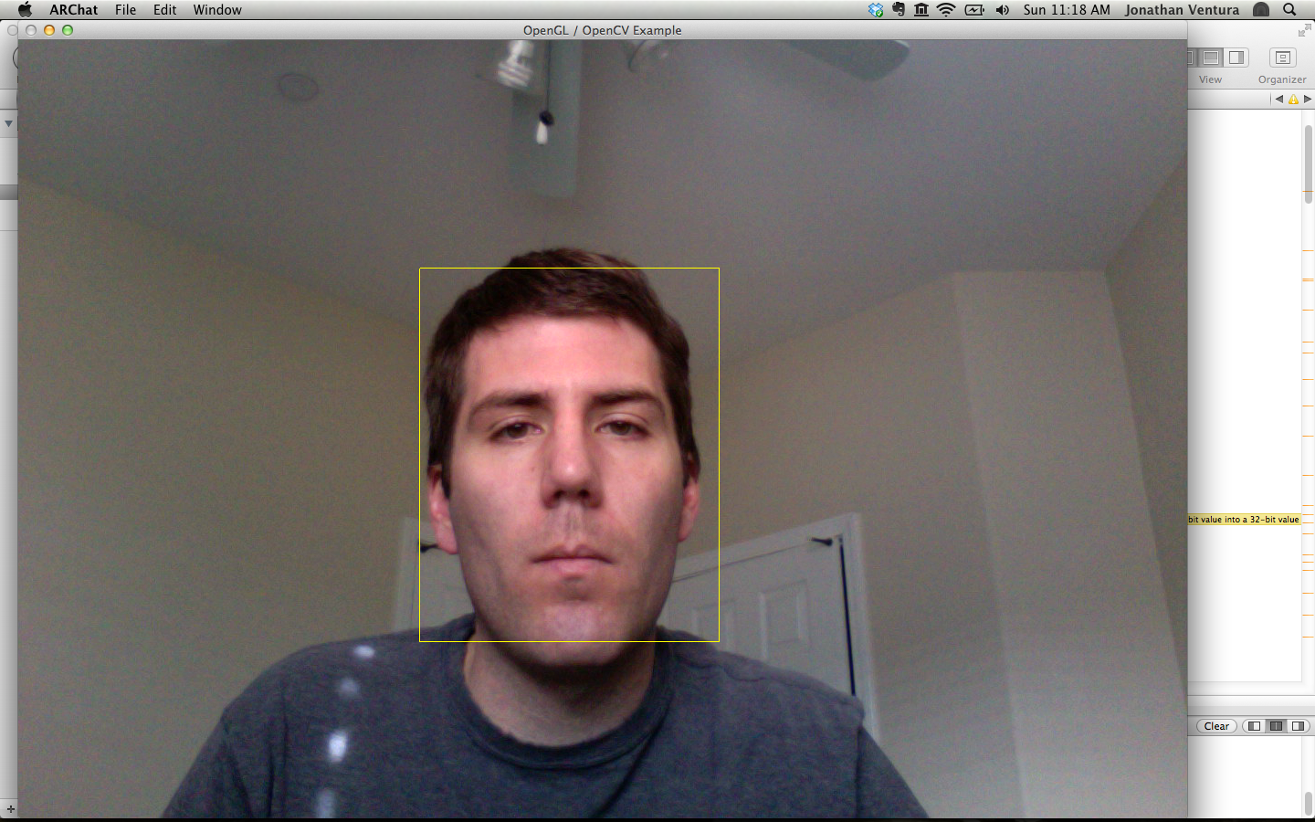
The face detector should return a rectangle covering your face, but it does work
differently on different people. Fix the height and width of the rectangle by
scaling it as necessary to cover your face approximately.
Finally, display a yellow rectangle around the face in the camera image. Toggle
the rectangle using the 'r' key.
3. From 2D to 3D
Now that you have detected the face, you will create an augmented reality
experience by rendering a 3D object which spins around the head of the viewer.
First, you must determine the 3D position of the head based on the 2D rectangle
given by the face detector. You need several pieces of information to determine
this:
1. The intrinsic parameters of the camera (found in the previous assignment).
2. The height of your head in centimeters (measured by you).
3. The height of your face as seen by the camera (given by the face detector).
Using the basic projection equation,
x = fx X / Z + u
y = fy Y / Z + v
you can determine the distance from the camera to your head.
Figuring out how to determine the value of Z (the camera distance to the head)
from the above observations is part of this assignment. Once you have the
depth, you can also determine the 3D locations of the four corners of the
rectangle given by the face detector, and the center point of the rectangle.
Now that you have the 3D coordinates of the head, use OpenGL to render red 3D
points at the four corners of the rectangle. The projection should exactly match
the 2D yellow rectangle which you drew in the previous step. The red 3D points
should be toggled with the 'r' key.
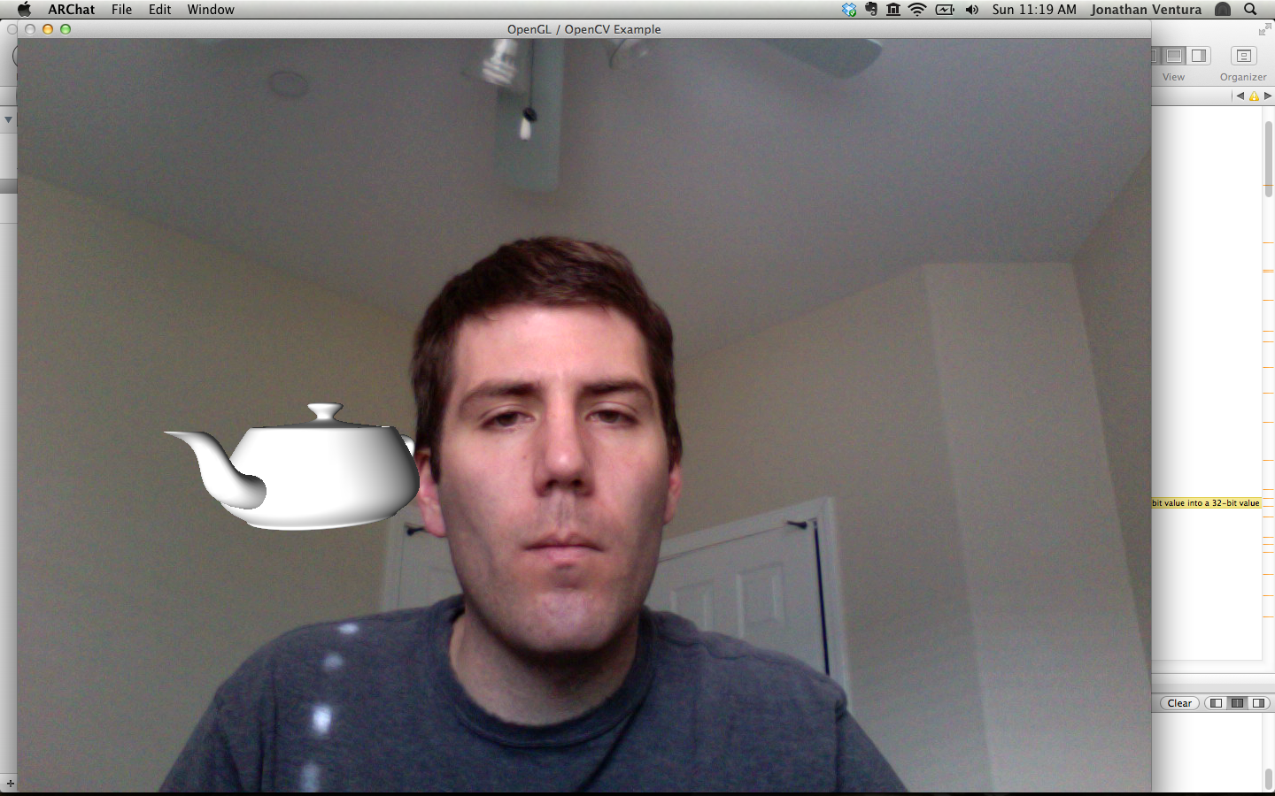
4. Spinning Teapots
Render a teapot which spins around the center point of the head. This
should be toggled with the 'o' key. By default, OpenGL renders flat shaded
polygons. Turn on OpenGL lighting by enabling GL_LIGHTING, GL_LIGHT0 . Also, use
the color-material commands to specify the material of the teapot when calling
glColor(). Enable GL_COLOR_MATERIAL and use the
glColorMaterial() function for
front and back faces, and ambient and diffuse components. Be sure to disable
these afterwards.
The trick here is to simulate the teapot being occluded by the head. This effect
can be achieved using the OpenGL depth buffer. Make sure to allocate the depth
buffer during GLUT initalization using the GLUT_DEPTH flag. Enable depth
buffering using glEnable( GL_DEPTH_TEST ). This should only be enabled during
teapot rendering, and disabled afterwards.
Before rendering the teapot, render a 3D filled rectangle around the head, but
render only to the depth buffer. Look at glColorMask() for an idea of how to do
this. Now, the teapot will be occluded by the phantom rectangle when it is
behind it.
Your code should also be able to render a cone or a torus instead of a teapot.
The user will step through the list of objects using the gesture recognizer
implemented in the next part.
5. Gesture Recognition
You will implement two different techniques to allow the user to activate a
button on the screen. You should set up two boxes to appear a the top left and
top right corners of the screen. The left box should be red, and the right box
should be green. When the red box is clicked, the system should select the
previous object in the list to render; the green box makes the system select the
next object.
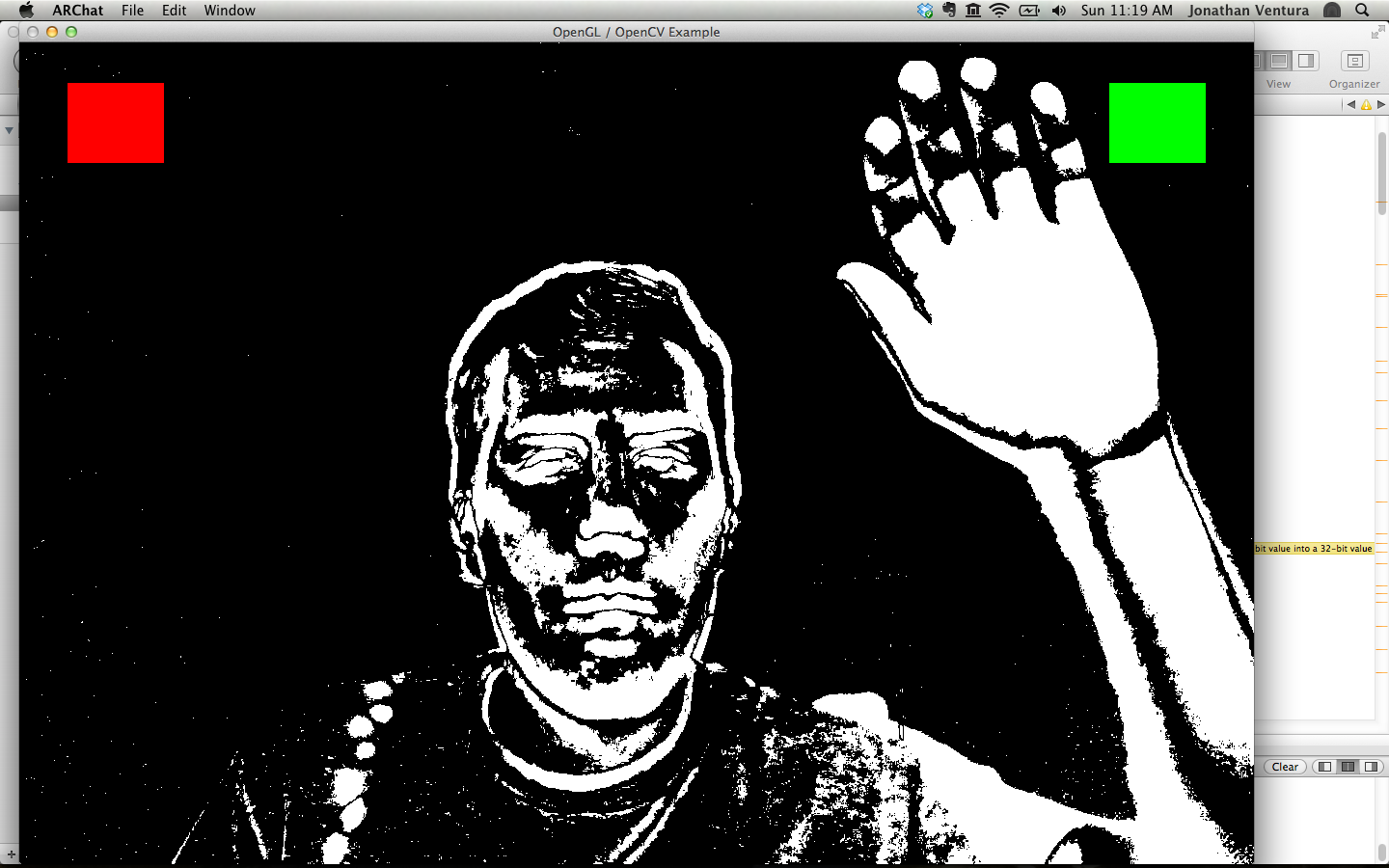
Image Segmentation by Background Subtraction
The first technique is to use background subtraction. The concept of background
subtraction is to compare the current camera image to a background image, and
use the difference to label each pixel as either background or foreground.
First capture and store a background image when the 'b' key is pressed. Use the
down-sampled grayscale image you created for face detection.
At each frame, compute the per-pixel absolute difference between the current
image and background image. Resize the absolute difference image back to full
size. Then threshold each pixel by 10 to separate background from foreground.
(There are OpenCV functions to perform these tasks.)
When the 'g' key is pressed toggle the display of the thresholded absolute
difference image instead of the camera image.
Now, detect when a button is clicked by counting how many foreground pixels
there are in the box. This can be performed in one line using OpenCV. When the
number of foreground pixels in a box changes from zero, that box is clicked.
Change the color of the box to yellow when there are foreground pixels in the
box.
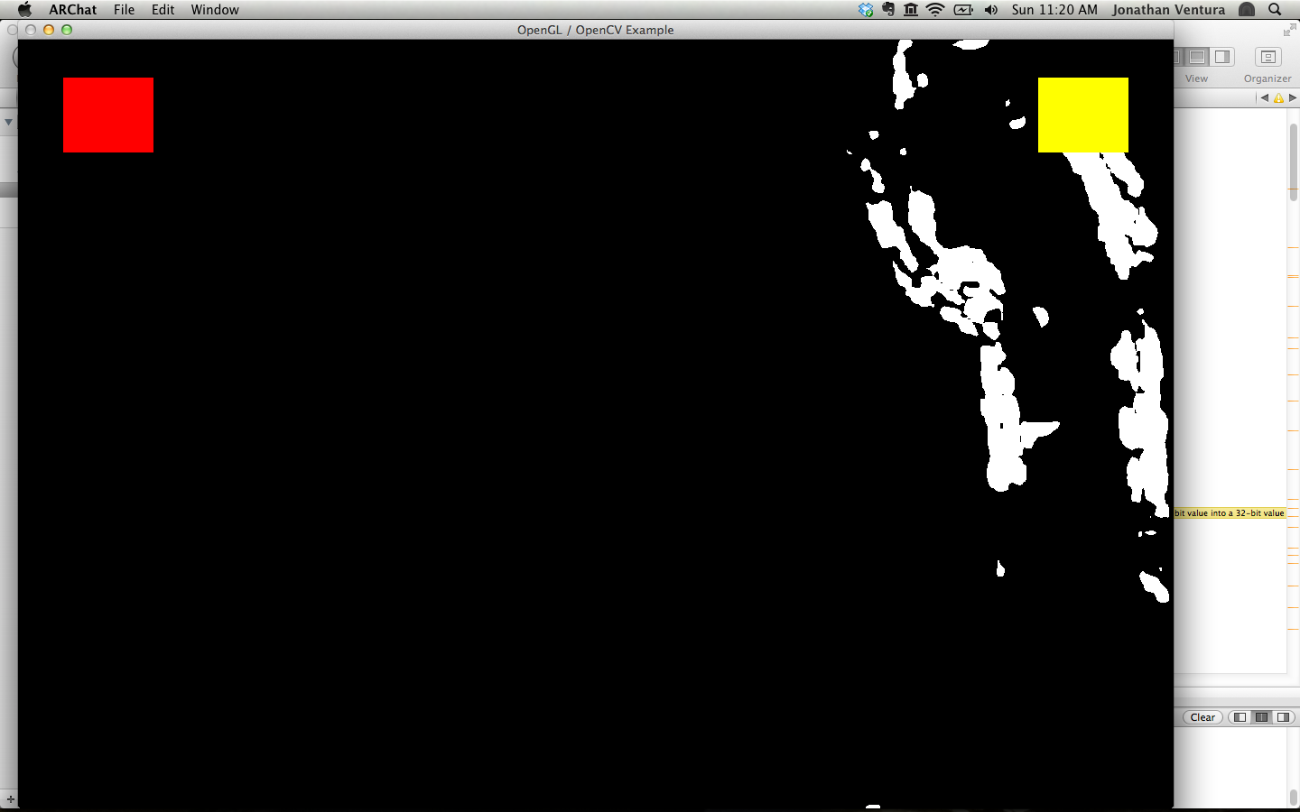
Motion Detection with Optical Flow
Our second technique for gesture recognition is to use optical flow. Optical
flow is a classical computer vision technique for determining the movement of
pixels between two images. The flow image represents the motion vector for each
pixel between the previous frame and the current frame.
Use the OpenCV function calcOpticalFlowFarneback() to compute the flow between
the previous frame and the current frame. Again, use the downsampled image,
because this is a computationally expensive task. Use pyramid scale 0.5, one
pyramid level, a window size of 3 pixels, one iteration, polyN = 5 and polySigma
= 1.1 .
Now, compute the magnitude of the flow vector at each pixel location. You will
need to iterate over the pixels in the flow image and compute the L2 norm of the
vector. Resize the flow magnitude image back to full size. Then, threshold the
flow magnitude by 10 to find pixels of significant motion.
This thresholded image can be used as in the previous part to determine when a
button is clicked.
The 'f' key should switch between the background subtraction and optical flow
techniques. The 'g' key should toggle display of the thresholded flow magnitude
image.
Here are Quicktime movies of some test sequences:
ARChatTest1.mov, ARChatTest2.mov
The thresholds for both background subtraction and
optical flow may have to be adjusted to get reasonable performance with the
selection (try e.g. 40 instead of 10 for background subtraction and 20 instead
of 10 for optical flow).
As calibration values for the camera that took these
videos, please use:
focal length fc: 684.58685 685.28020
principal point cc: 281.92771 238.46315
distortion (k1,k2,p1,p2): 0.03096 -0.15837 0.00213
-0.00555
and you can use 15 for the face height (not that
it makes a difference what number you use, since all that it does is
pick a unit for real world measurements, but we asked you to use cm and
that's approximately the right value in cm).
Submission
Use Gauchospace to submit all files (including code and a README.TXT describing your approach, any difficulties
you had, and all external sources you used).