
up:
Chapter 10 -- Initialization
prev: Chapter 10 -- Initialization
next: 10.2 Software Initialization for Real-Address Mode
DX holds a component identifier and revision number after RESET as Figure 10-1 illustrates. DH contains 3, which indicates an 80386 component. DL contains a unique identifier of the revision level.
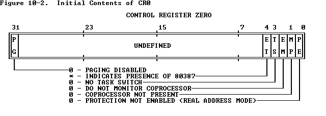
Control register zero (CR0) contains the values shown in Figure 10-2 . The ET bit of CR0 is set if an 80387 is present in the configuration (according to the state of the ERROR# pin after RESET). If ET is reset, the configuration either contains an 80287 or does not contain a coprocessor. A software test is required to distinguish between these latter two possibilities.
The remaining registers and flags are set as follows:
   EFLAGS             =00000002H
   IP                 =0000FFF0H
   CS selector        =000H
   DS selector        =0000H
   ES selector        =0000H
   SS selector        =0000H
   FS selector        =0000H
   GS selector        =0000H
   IDTR:
              base    =0
              limit   =03FFH
All registers not mentioned above are undefined.
These settings imply that the processor begins in real-address mode with interrupts disabled.
up:
Chapter 10 -- Initialization

prev: Chapter 10 -- Initialization
next: 10.2 Software Initialization for Real-Address Mode