An Introduction to Performance Analysis
and SmartBits from Netcom Systems
Performance Analysis
Smartbits
Basic Setup Overview
Example #1
Example #2
Example #3

Basic SmartBits Configuration


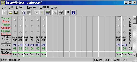
There are several software applications available with SmartBits, the main one which I will focus on is called SmartWindow and it runs on a Windows 9x platform.  Communication with the SmartBits unit is across a serial link (Com Port).  After you have selected the proper com port for the program to communicate with the SmartWindow application will query the SmartBits unit across the link and return the Appropriate display panel, shown left.  This will serve as the main window for communicating with the unit.
This main window displays the detected interface cards, along with some configuration and status information.  From here we can control each card individually based on its specific functionality.  We can start and stop traffic on each card individually or we can assign cards to a group and control the group as a whole. The graphical description of each card also serves as a button which will open a card specific menu. (card 19, model 7710 shown right)  From this card menu we have several options.  The first option that we are going to explore is Transmit Setup, but we will also explore Layer 3 Setup, and the use and functionality of the counter buttons should be intuitive.
The transmit setup menu displays the list of current Virtual Transmit Engines (VTEs), and their settings.  From here we can activate or deactivate or delete any VTE.  It is necessary that the SmartMetrics Mode tab is enabled in the bottom left corner, in order to utilize VTEs.  The button labeled This Port (shown below right) is used to configure the packet rates for the offered load as well as error generation settings.  There are nice features included for editing VTEs collectively such as the copying, pasting, and incrementing tools provided from this menu.  We can manipulate each VTE individually by double clicking on it. 

For each VTE we can specify the size, fixed or random, along with the packet type. 
By selecting edit from the Transmit Setup window shown above we can manipulate the protocol header field values one by one.  We will be using IP packets for this experiment, and the availabale header fields are displayed.  Here we will place the MAC address of the next hop in the MAC Dest field, followed by our own made up MAC address in the MAC Src.  Additionally the SourceIP and DestIP fields must be filled in with the appropriate information.  The rest of the fields are up to the experimentor to adjust as desired.
Coming back to the Layer 3 Setup, here we can specify the MAC address of our card along with the basic IP address, Netmask, and Gateway.  We can select a ping target, time intervals, and choose whether or not we want to reply to all ARP requests.
After we have set up our VTE(s) and Layer 3 information we are ready to start some traffic.  In a packet forwarding situation we might be sending traffic out card 19 through intermediate routers and back in card 20 and vice versa.  In this case after setting all the proper MAC and IP settings in the SmartBits and the VTE(s), we may want to display the counters for the two cards.  Now we can start and stop the traffic in either direction, and if all routing is performed as expected, we will see the counters for the Transmitter and the Receiver reflect the forwarding performance of the router(s). 


Performance Analysis
Smartbits
Basic Setup Overview
Example #1
Example #2
Example #3